
NDT Services
FLUORESCENT DYE LEAK TEST
It’s a method in which a small amount of fluorescent dye is injected into condenser shell side or any operating system and circulated with the mixture of water.
The dye get mixed with water and ready to escape and accumulate at all leak sites. By then scanning the system with a leak detection lamp, all leaks will fluorescent green or yellow, making them easy to spot.
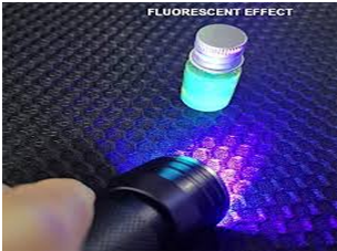
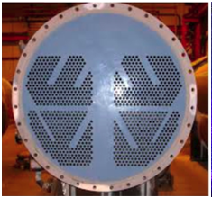
Depending on the size of your system, it can take anywhere from 5-45 mins.
Its eco- friendliness and We care about your health as well as the health of our planet. The materials used in the dyes consist of completely organic-free fibers. It makes our leak detection dyes different from conventional dyes that have co-solvents. Due to its materials, after half a year in the ground our dyes will fully degrade without any harm to nature. The second important thing is that we do not use any chemically aggressive liquids, which can damage one’s health. And finally, UV lamps consume only 10W, which equals to the power of a simple light bulb. In this day and age, energy saving not only has economic benefits, but also enables us to reduce consumption of natural resources as well as emission of harmful substances into the atmosphere.
ONLINE/OFFLINE HELIUM LEAK DETECTION TESTING
OFFLINE HELIUM LEAK TESTING OF HYDROGEN COOLED GENERATOR/STATOR WATER COOLED CONNECTION AT BAR END
Helium leak testing is used to find small leaks or larger leaks in bigger volumes. The helium is used as a tracer gas and its concentration is measured. This guide to helium leak testing should outline the basics of using this leak testing method.
First of these is to mix the helium with another lower cost gas, either nitrogen or compressed air. This is only possible where the sensitivity of the test is not compromised by the mixing process.
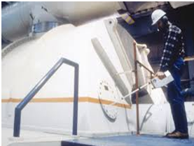
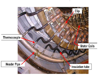
Helium leak testing can be done at Stator water cooling connection at bar end.
Experience has identified typical problem areas, the most important among them being 1) leaks of hydrogen into the stator cooling water, 2) leaks of stator cooling water out of the winding, 3) plugging of the coolant path in the winding, and 4) clogging of the coolant path outside the winding.
IDENTIFYING TUBE LEAKS IN CONDENSERS / HEAT EXCHANGERS BY VACUUM PULLING
Our system can very effectively identify tube leaks also. The procedure adopted here is that Helium gas is sprayed into the tubes and if a leak is present, it will be carried over into the steam side of the Condenser, which is under vacuum condition and then get ejected out through the ejector / vacuum pump, where the ejected gases are tested for presence of helium using the sensitive spectrometer.
The advantage of Helium Leak Detection is that, the check for tube leaks can be done by reducing the load of the machine and isolating one half of the condenser at a time. The test can also be conducted off-line, but the vacuum on the steam side should be maintained using the vacuum pumps and also with steam dumping.
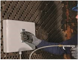
ONLINE HELIUM LEAK TESTING OF CONDENSER NEGATIVE PRESSURE PART/AIR INGRESS
Our procedure involves spraying of a tracer gas – Helium on all the suspect areas. Helium being a lighter gas than air, gets sucked into the system due to difference in pressure in case a leaking spot is present. Helium which got sucked into the negative side of the Condenser is then sucked out through the air removal system along with the non-condensable and a sample of this ejected mixture is passed through our Mass Spectrometer to identify presence of Helium. As the Spectrometer is extremely sensitive, even minute leaks can be identified instantaneously. We will categorize the leaks as Small, Medium, Large and Very Large. This classification will help in planning the maintenance program.
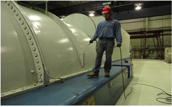
EDDY CURRENT TESTING OF FERROUS & NON-FERROUS TUBES
EDDY CURRENT TESTING OF NON-FERROUS TUBES
Tritech Industrial Services undertakes Eddy Current Testing services, a Non-Destructive Testing (NDT) that aims at detection and characterization of defects/ Flaws/discontinuities in non-ferrous tubes. Eddy Current Testing (ECT) is an electromagnetic NDT Technique widely used in Power Plants, Petro- Chemical, Refineries and other Industries for Tubular Heat Exchangers, Coolers, Condensers.
Eddy current testing is a well-established method of non-destructive testing that is used to examine nonferrous/nonmagnetic materials such as condenser and heat exchanger tubes in power generation plants. Eddy current testing reveals discontinuities in tubing, provides plant engineers with an accurate assessment of a unit’s condition, and is a tool for predicting the remaining useful life of the tubes.
Along with condenser and heat exchanger tube cleaning and leak detection applications, many power generations plants with aging units include eddy current testing in plant maintenance programs in an overall effort to maximize the efficient life of their units.
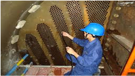
- Eddy Current is a cost effective and reliable way toinspect tubing.
- Inspect non-ferromagnetic tube and materials.
- Condensers, feed water heaters, air conditioners,chillers, and other heat exchangers
- Detection and sizing of metal discontinuities such ascorrosion, erosion, tube-to-tube wear, pitting, fretting,cracks, etc.
- Multi-frequency inspection with mixing and filteringcapabilities.
- Data is recorded and archived which will allow you totrack the corrosion rate for each tube.
REMOTE FIELD EDDY CURRENT TESTING (RFET)
- Full wall inspection of ferromagnetic tubes
- Used for the detection and sizing of wall thinning caused by corrosion,erosion, wear, pitting and baffle cuts.
- Used to inspect boilers, feed water heaters, air coolers, and carbon steel heat exchangers.
NEAR FIELDEDDY CURRENT TESTING (NFET)
- Inside diameter testing only
- Detect corrosion, erosion and pitting inside carbon steel tubing
- Unaffected by external structures such as tube sheets and support plates.
- Used to inspect Fin tube heat exchangers
INTERNAL ROTATING INSPECTION SYSTEM(IRIS)
IRIS is an ultrasonic technique used for the inspection of awide range of materials, including both non-ferromagnetic andferromagnetic tubing.
- Allows for the detection and sizing of wall loss as a result of corrosion,erosion, tube-to-tube wear, pitting, fretting,cracking and baffle cuts.
- Focused ultrasonic probe and a rotating mirror to producea helical scan.
- Ultrasound is reflected from the tube ID and OD and thetime difference isused to calculate the thickness.
- IRIS is a great backup and verification tool for the othertube inspection techniques.
- IRIS data to be presented as a B, C, or D-scan image.
PAET
Eddy current arrays (ECA) are the natural extension of ECT. ECAs are composed of arrays of coils that activate in sequences intended to eliminate interference between them. The array slides on top of surfaces, offering an overall wider coverage and better sensitivity to defects than conventional ECT. ECA technology can detect surface-breaking defects and, to some extent, subsurface defects. ECA probes can also be shaped to match more “exotic” geometries, which enable single-pass scanning of geometries that traditionally pose serious challenges to other inspection technologies. CA technology is used as an alternative to other surface inspection technologies in such industries as the oil, gas, and petrochemical industry; the power generation and nuclear industries; the aerospace industry; and the heavy equipment and mining industries. ECAs also very successfully supplement ultrasonic testing (UT) and phased-array UT because these suffer from what is often referred to as a “dead zone” near the surface, making it difficult for them to detect near-surface defects.
Therefore, surface applications of ECA technology are numerous, ranging from weld inspection on pressure vessels and pipes.
Eddy current array (ECA) technology for gear testing incorporates several traditional bridge or reflection (driver-pickup) probe coils in order to achieve a much larger coverage in a single inspection pass. Single Coil Raster Scanning is either slow or misses most of the surface.
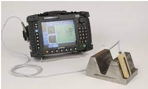
Eddy current arrays (ECA) are the natural extension of ECT. ECAs are composed of arrays of coils that activate in sequences intended to eliminate interference between them. The array slides on top of surfaces, offering an overall wider coverage and better sensitivity to defects than conventional ECT. ECA technology can detect surface-breaking defects and, to some extent, subsurface defects. ECA probes can also be shaped to match more “exotic” geometries, which enable single-pass scanning of geometries that traditionally pose serious challenges to other inspection technologies. ECA technology is used as an alternative to other surface inspection technologies in such industries as the oil, gas, and petrochemical industry; the power generation and nuclear industries; the aerospace industry; and the heavy equipment and mining industries. ECAs also very successfully supplement ultrasonic testing (UT) and phased-array UT because these suffer from what is often referred to as a “dead zone” near the surface, making it difficult for them to detect near-surface defects.
Therefore, surface applications of ECA technology are numerous, ranging from weld inspection on pressure vessels and pipes.
BORESCOPE/VIDEOSCOPE INSPECTION
Borescopes are commonly used in the visual inspection of aircraft engines, aeroderivative industrial gas turbines, steam turbines, diesel engines, and automotive and truck engines. Gas and steam turbines require particular attention because of safety and maintenance requirements. Borescope inspection of engines can be used to prevent unnecessary maintenance, which can become extremely costly for large turbines. They are also used in manufacturing of machined or cast parts to inspect critical interior surfaces for burrs, surface finish or complete through-holes.
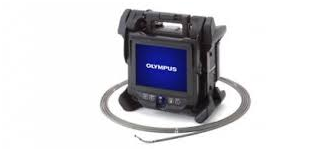
A borescope is an optical device consisting of a rigid or flexible tube with an eye piece and an objective lens on the other linked together by a relay optical system in between.
Fiber optics Inspection (Borescope) is a remote visual examination technique/tool for determining the presence of internal defects including internal cracks, intensity of corrosion or erosion, oxidation or internal deposits, degree of damage, pitting and presence of foreign objects etc.in any directly inaccessible area of component through Inspection hole, tube cutting opening and its other integral parts etc.
The optical system in some instances is surrounded by optical fibres usedfor illumination of the remote object.
An internal image of the illuminated object is formed by the objective lens and magnified by the eye piece which presence it too the viewers eye. Rigid or flexible borescope may be fitted with an imaging or video device.
Objective
Boiler high-pressure parts were subjected to remote visual inspection i.e. Fiberscope. Based on the specific requirements of the client, the general objectives of this inspection are:
- To examine the condition of internal surface of pressure parts.
- To determine the presence of internal defects including cracks, intensity of erosion, corrosion, pitting or presence of foreign objects such as dust agglomerates, welding/grinding chips, other extraneous matter in the locations for examination.
RLA STUDIES, ADVANCED AND CONVENTIONAL NDT
RLA STUDIES
We undertake comprehensive Remnant Life Assessment (RLA) Study as per Indian Boiler Act 1950 is most essential & most useful in boilers of Thermal Power Plant, Sugar Factories & Refineries to control over proper Boiler Operation for safe & economy. Forconducting RLA Studies, the methods & techniques should be selected carefully. We do services in India and abroad. High end metallurgical expertise and a unique understanding of damage mechanisms provide us a distinct acceptance to end users. Due to continuous use under high pressure and temperature, material properties degrade and effective life is consumed. The major degradation process is creep of the material which occurs under high temperature and pressure. Based on code and standards, the power plants and boilers are designed for 15- 30 years of the creep life. Thermal and creep degradation of material reflects in microstructure; hence it is useful to estimate Remaining life. The other degradation mechanisms are fatigue and delayed cracking of the weld due to fabrication related defects as they open up after several years of service. Creep is an irreversible damage. An onset of creep if it is in final stage the component needs to be retired from the plant otherwise it can lead to catastrophic failure. However, in case of localized damages like cracking in the weld or flange or bend which can be replaced or repaired depending upon the nature of the problem. In case of any localized problem is observed, it can be rectified and overall integrity of the system can be improved. RLA defines the inspection period and maximum life before the next inspection. It can be predicted up to 5 years. RLA studies give great benefit to operating plants as they can plan their inventory and components spares as well as suggestion on operation which can prevent damages. By adopting this philosophy, advanced countries have extracted the life of a power plant or process plant from 1.5 to 2 times then the original design life.
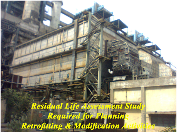
Need for RLA of Boilers
Increasing cost of new equipment and diminishing resources
Extended lead time in plant construction
Stringent environmental, safety and other regulations
Increasing awareness of the technological feasibility of extendingcomponent life
Reasons for Remaining Life Estimation Study
The high temperature operations of pressure parts are subjected to creep stress at elevated pressure.
The starting and stopping of the Boiler Unit results in fatigue stress
The fuels burnt can cause corrosion in various areas in the boiler
The water used for steam generation leaves deposits inside the tube which increases the metal temperature leading to long term overheating.
Residual stresses during manufacturing, the vibrations due to flow over the tube, mechanical vibrations, erosion due to the abrasive nature of the fuel etc. do occur in a boiler.
When a boiler is operated beyond the specified operating parameters.
All of the above, individually or combined, lead to material degradations of different magnitude and will lead to a failure unless RLA is not carried out.
ADVANCED NDT
PAUT/TOFD INSPECTION
Phased Array Ultrasonic Testing (PAUT) is an advanced non-destructive examination technique that utilizes a set of ultrasonic testing (UT) probes made up of numerous small elements, each of which is pulsed individually with computer-calculated timing. This technique can be used to inspect more complex geometries that are difficult and much slower to inspect with single probes. PAUT can be used to inspect almost any material where traditional UT methods have been utilized, and is often used for weld inspections and crack detection
Compared to other forms of UT, PAUT has several advantages. PAUT can be conducted more quickly than other forms of UT, often within a fraction of a second. It can easily be used for repeat scans because it has a high degree of repeatability. By emitting beams of multiple different angles sequentially, PAUT is able to create detailed and accurate cross-sections of a part. It is also particularly useful in situations where there is less room for mechanical scanning because it’s able to sweep the beam without moving the probe.
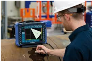
TOFD is usually performed using longitudinal waves as the primary detection method. Ultrasonic sensors are placed on each side of the weld. One sensor sends the ultrasonic beam into the material and the other sensor receives reflected and diffracted ultrasound from anomalies and geometric reflectors. TOFD provides a wide area of coverage with a single beam by exploiting ultrasonic beam spread theory inside the wedge and the inspected material. When the beam comes in contact with the tip of a flaw, or crack, diffracted energy is cast in all directions. Measuring the time of flight of the diffracted beams enables accurate and reliable flaw detection and sizing, even if the crack is off-oriented to the initial beam direction. During typical TOFD inspections, A-scans are collected and used to create B-scan (side view) images of the weld. Analysis is done on the acquisition unit or in post-analysis software, positioning cursors to measure the length and through-wall height of flaws.
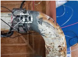
MAGNETIC FLUX LEAKAGE (MFL)
- Inspection technique suitable for wall-loss detection and measurement of sharp defects, such as pitting, grooving,
and circumferential cracks. - Applicable to ferromagnetic tubing
- Effective for testing aluminium-finned carbon steel tubes because the magnetic field is mostly unaffected by the fins.
- A good Back-up inspection to Remote Field Testing.
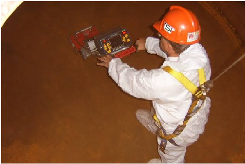
CONVENTIONAL AND OTHER NDT SERVICES
Your content goes here. Edit or remove this text inline or in the module Content settings. You can also style every aspect of this content in the module Design settings and even apply custom CSS to this text in the module Advanced settings.